Fortunately for us and our wallets is that one particular company just flooded the market with a cheap color alternative with better resolution to boot. I figure you can make small color games at true 8-bit and larger games using the 4 color mode of black, grey, dark grey, white.
Here are parts plus prices::: note prices US
Teensy 3.2 with 256k ram and 32-bit processor $20.00-25.00
Inhaos LCD 2000_7775 $ 4.99
Tactile buttons $ 5.00
Prototype circuit board X 2 ¢ .75
Charger $ .99-4.99
Step up $ .99-4.99
Or powerboost 500 $ 20.00
Micro SD card reader $ 2.50
Wire $ 2.50
As you can see unless you buy the powerboost 500 which is a step up and charger the materials are pretty cheap. I buy in bulk when I can but all prices are for a single piece.
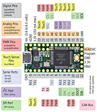
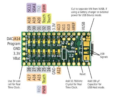
Ok so here's a pic of the system so far. The teensy 3.2 has 10 extra digital io pins so the expansion buttons you see will be ready to use when ever you are ready to program them.
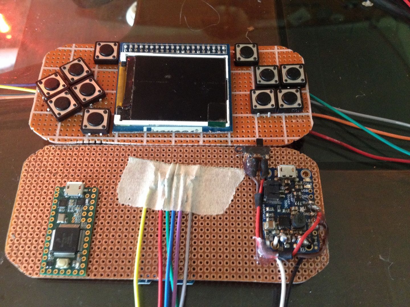
All right so here is the part I need help with.
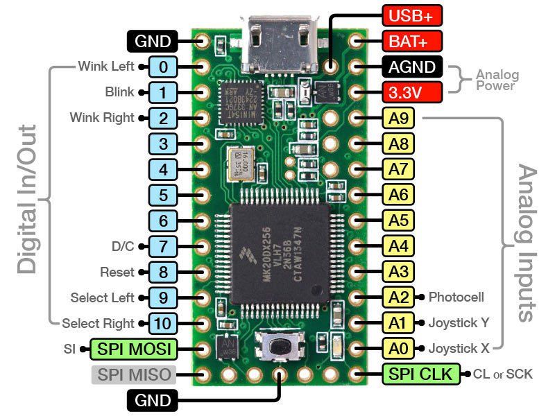
I'm trying to figure out which pins are actually what on the LCD. As you can see it's missing a couple from the settings file in the GB library. Now the pinouts in the 7775's library define the pin out as
- Code: Select all
// pin definition for uno
#define CS     11
#define wr     10
#define rs      12
//#define LE  13

//Plus a whole bunch of data pins that I don't think are needed
But I can see from the schematic there are more that need to be connected to the MCU.
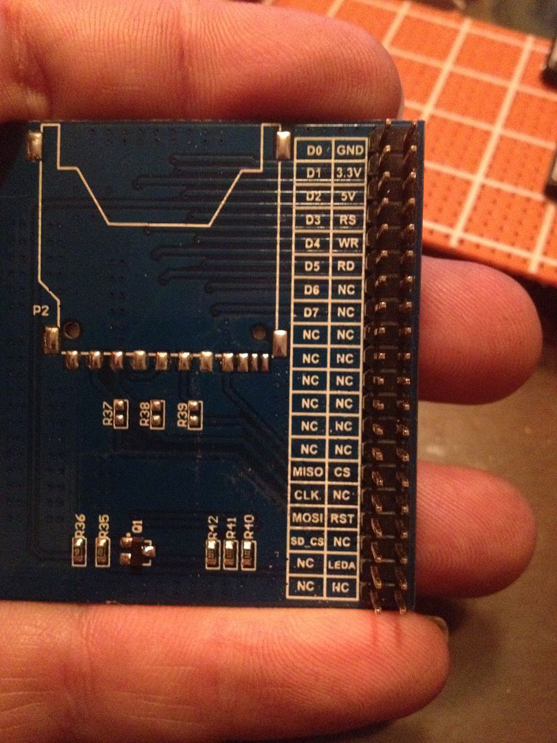
I've got the pins above except for LE, I think it's the Leda pin but not sure.
Here's what I have hooked up to the screen
5v
Ground
Wr
CS
Rs
Rst
Mosi
Clk
I think I need miso too but can't really tell. Also am I right that the SCK pin on the arduino gets 3 different wires? That's what I'm reading from the schematic at least.