Can someone please clue me in about the crystal n the Gamebuino schematics?
Guess not. I just can't believe no one knows the answer?
Advanced Gamebuino prototype
Re: Advanced Gamebuino prototype
![]() by Duhjoker » Sat Sep 10, 2016 9:56 pm
by Duhjoker » Sat Sep 10, 2016 9:56 pm
Last edited by Duhjoker on Sun Sep 11, 2016 10:37 pm, edited 1 time in total.
-

Duhjoker - Posts: 446
- Joined: Sat Jul 02, 2016 4:57 am
- Location: Where Palm trees grow
Re: Advanced Gamebuino prototype
![]() by Zvoc47 » Sun Sep 11, 2016 10:03 pm
by Zvoc47 » Sun Sep 11, 2016 10:03 pm
I have this display too. I'm not sure how to connect it. I tried with the schematics on eBay, but I think I've broken it with 5V. It really tricked me when it said 5V which I thought was the power for the display while in fact it was the background LED. That doesn't make sense. If an Arduino works on 3.3V to satisfy the screen's VCC, why would it have a 5V power supply? Can you please tell me how you wired this thing?
- Zvoc47
- Posts: 56
- Joined: Mon Oct 05, 2015 10:03 pm
Re: Advanced Gamebuino prototype
![]() by Duhjoker » Sun Sep 11, 2016 10:15 pm
by Duhjoker » Sun Sep 11, 2016 10:15 pm
Still kinda working on that........but if you open the the LCD_2000_7775.h and then go to hardware and choose the adafruit_gfx.h. You should find what you need there.
That's what I have used but as I haven't fixed the color library yet I have no way to test. I don't think you blew the LCD using the 5v-in, I've supplied 5v to the 5v und and it comes on.
Edit
What MCU are you using?
I don't really understand why you can't open up cpp files using arduino since it uses cpp files as libraries but you will need visual studio. I use 2015. Make you a free Microsoft account and it will bypass the trial period blocker.
Edit 2
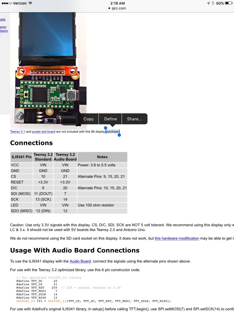
Here's a pic of how to hook up a similar screen made by pjrc. But it's using a teensy.
Edit 3
I don't know about connecting RST to 3.3v, I would use a SS pin
That's what I have used but as I haven't fixed the color library yet I have no way to test. I don't think you blew the LCD using the 5v-in, I've supplied 5v to the 5v und and it comes on.
Edit
What MCU are you using?
I don't really understand why you can't open up cpp files using arduino since it uses cpp files as libraries but you will need visual studio. I use 2015. Make you a free Microsoft account and it will bypass the trial period blocker.
Edit 2
Here's a pic of how to hook up a similar screen made by pjrc. But it's using a teensy.
Edit 3
I don't know about connecting RST to 3.3v, I would use a SS pin
-
Duhjoker - Posts: 446
- Joined: Sat Jul 02, 2016 4:57 am
- Location: Where Palm trees grow
Re: Advanced Gamebuino prototype
![]() by rodot » Mon Sep 12, 2016 7:52 am
by rodot » Mon Sep 12, 2016 7:52 am
The 16Mhz crystal on the Gamebuino board gives the clock to the main MCU, the ATMEGA328P, so it runs at 16 millions instructions / second.
These kind of screens usually work @3.3V... but when you buy a module on ebay, there are often level shifters to allow it to run at 5V. I've seen some that must be powered at 5V but the logic can be both 3V3 or 5V thank to the level shifters. You can say by looking at the PCB : are the screen's pin directly broken out or do they go through components ? A picture of the back of your screen could help.
On the modules I used, the backlight LEDs are powered by VCC (5V) and controlled by the BKL pin using a transistor. You can just tie it to GND if you want to keep the backlight ON or drive it using a pin. You can use a PWM pin to change the backlight intensity using AnalogWrite(). All that depends on the module you are using, so check twice
The .CPP (or .C or .H) files aren't opened by the Arduino IDE, but you can put some alongside your .ino file and #include them, so they will be included and compiled (it's what you do when you include a library). You will have to edit these files using an external editor, you can use your notepad, but there are better options like notepad++ or atom. Or you can use another IDE which allow to open everything (.ino, .cpp...) : there is a free Community Edition of Visual Studio and the Visual Micro plugin allows you to compile and upload your code. You can also use NetBeans with a plugin, or PlatformIO... there are plenty to choose from.
-

rodot - Site Admin
- Posts: 1290
- Joined: Mon Nov 19, 2012 11:54 pm
- Location: France
Re: Advanced Gamebuino prototype
![]() by Duhjoker » Mon Sep 12, 2016 8:05 am
by Duhjoker » Mon Sep 12, 2016 8:05 am
Thanks for the reply i appreciate it!!
-
Duhjoker - Posts: 446
- Joined: Sat Jul 02, 2016 4:57 am
- Location: Where Palm trees grow
Re: Advanced Gamebuino prototype
![]() by Zvoc47 » Tue Sep 13, 2016 2:39 pm
by Zvoc47 » Tue Sep 13, 2016 2:39 pm
I'm asking about the Inhaos ST7775 display, not ST7735. I do have ST7735, though, and it works well. I've been using it with an Arduino Duemillanove derivative called Croduino.
- Zvoc47
- Posts: 56
- Joined: Mon Oct 05, 2015 10:03 pm
Re: Advanced Gamebuino prototype
![]() by Duhjoker » Tue Sep 13, 2016 7:56 pm
by Duhjoker » Tue Sep 13, 2016 7:56 pm
Who mentiined any thing about a st7735?
Plus i could help you better if i knew the answers to the questions i asked above. Can't help unless I know what hardwares you are using.
Plus i could help you better if i knew the answers to the questions i asked above. Can't help unless I know what hardwares you are using.
-
Duhjoker - Posts: 446
- Joined: Sat Jul 02, 2016 4:57 am
- Location: Where Palm trees grow
Re: Advanced Gamebuino prototype
![]() by Zvoc47 » Wed Sep 14, 2016 2:17 pm
by Zvoc47 » Wed Sep 14, 2016 2:17 pm
In the first post, I saw the ST7775 display and I said that I somehow broke it with 5V of the Arduino Duemillanove (Croduino).
- Zvoc47
- Posts: 56
- Joined: Mon Oct 05, 2015 10:03 pm
Re: Advanced Gamebuino prototype
![]() by Duhjoker » Wed Sep 14, 2016 8:10 pm
by Duhjoker » Wed Sep 14, 2016 8:10 pm
Zvoc47 wrote:I'm asking about the Inhaos ST7775 display, not ST7735. I do have ST7735, though, and it works well. I've been using it with an Arduino Duemillanove derivative called Croduino.
No mention of an st7735 before post above on this thread.
Im trying to understand why your screen shorted. It does use both 5v and 3.3v inputs, are you sure you didn't get the two confused?
If you look at the source code for your LCD specifically the adafruit_GFX, the LCD_2000_7775.h and match them to the gamebuinos display.h and settings.h, you will find which wires need to be hooked up to work the LCD. Now since your using a different MCU than a uno R3 you will have to do some research to figure out which pins on the arduino to connect the LCD to.
It basically uses the same pin system that the regular Gamebuino UNO R3 uses with a bunch of data pins which collect and display data to the screen like in bar graphs.
You won't need those data pins since it's taking in a different type of data. Look on the first page of this thread and you will see all relevant info that has been collected including what I wrote above.
When you do get it right please share your work.If your willing, I could use a lil help with my library.
-
Duhjoker - Posts: 446
- Joined: Sat Jul 02, 2016 4:57 am
- Location: Where Palm trees grow
Re: Advanced Gamebuino prototype
![]() by Zvoc47 » Thu Sep 15, 2016 9:16 pm
by Zvoc47 » Thu Sep 15, 2016 9:16 pm
Arduino Duemillanove has the ATMEGA328P microcontroller and it runs on 5V, but the eBay page of the Inhaos display ST7775 says that the I/O voltage is 3.3V or something like that. It cannot support 5V. This is why I think I broke the screen. I used the code that was in the downloadable zip file on the Inhaos website and uploaded it onto the board, but there was no picture. I tried using a lot of resistors (and failed with wrong wiring) to divide the voltage and still no success. Can you show me how you wired the Inhaos display? Can you take a picture of it?
By the way, I saw there's a shield of the display and for Arduino Uno, from Inhaos. I saw that there are lots of resistors on the I/O lines. This surely explains that resistors need to be used. I'm just going to buy a new display, a normal Arduino Uno board and the shield and see if it will work.
Are you using ATMEGA328P?
- Zvoc47
- Posts: 56
- Joined: Mon Oct 05, 2015 10:03 pm
Return to Hardware Development
Who is online
Users browsing this forum: No registered users and 4 guests