
Archive of the Gamebuino Classic forum (2014-2018), rebuilt from the pages kept by the Wayback Machine: only part of the topics and pages were captured. Read-only. Removal on request: hi@gamebuino.com.
Advanced Gamebuino prototype
Duhjoker Wed Aug 31, 2016 7:46 am
All right so I'm building an advanced Gamebuino prototype featuring a 32-bit processor with 256k ram and a color LCD. My idea is to create an advanced Gamebuino made from the least amount of parts that's also easy on the wallet while encouraging more building and better more complex gaming.
Fortunately for us and our wallets is that one particular company just flooded the market with a cheap color alternative with better resolution to boot. I figure you can make small color games at true 8-bit and larger games using the 4 color mode of black, grey, dark grey, white.
Here are parts plus prices::: note prices US
Teensy 3.2 with 256k ram and 32-bit processor $20.00-25.00
Inhaos LCD 2000_7775 $ 4.99
Tactile buttons $ 5.00
Prototype circuit board X 2 ¢ .75
Charger $ .99-4.99
Step up $ .99-4.99
Or powerboost 500 $ 20.00
Micro SD card reader $ 2.50
Wire $ 2.50
As you can see unless you buy the powerboost 500 which is a step up and charger the materials are pretty cheap. I buy in bulk when I can but all prices are for a single piece.
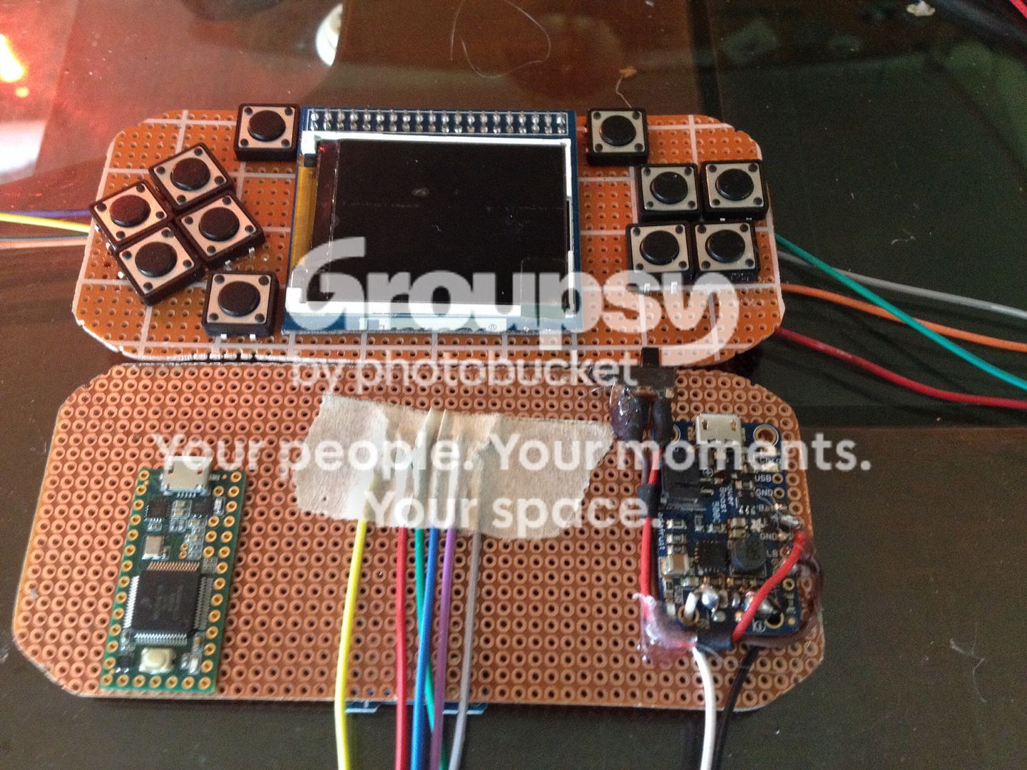
Ok so here's a pic of the system so far. The teensy 3.2 has 10 extra digital io pins so the expansion buttons you see will be ready to use when ever you are ready to program them.
All right so here is the part I need help with.
I'm trying to figure out which pins are actually what on the LCD. As you can see it's missing a couple from the settings file in the GB library. Now the pinouts in the 7775's library define the pin out as
But I can see from the schematic there are more that need to be connected to the MCU.
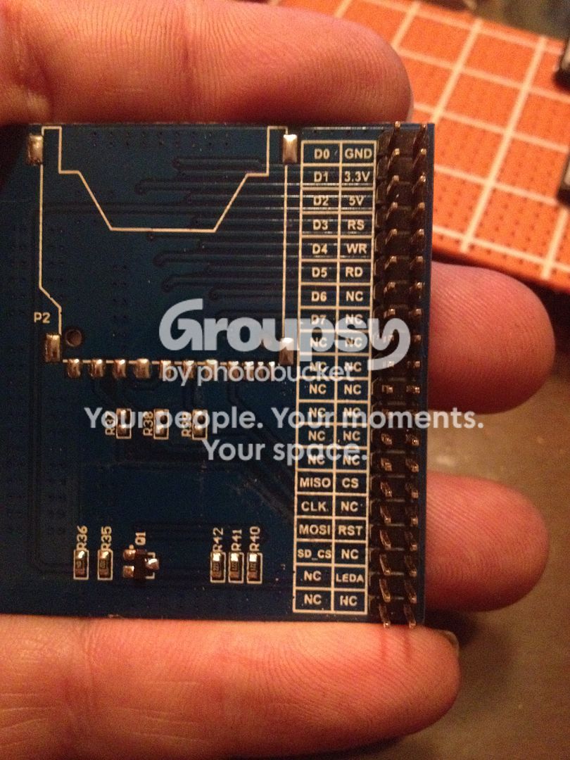
I've got the pins above except for LE, I think it's the Leda pin but not sure.
Here's what I have hooked up to the screen
5v
Ground
Wr
CS
Rs
Rst
Mosi
Clk
I think I need miso too but can't really tell. Also am I right that the SCK pin on the arduino gets 3 different wires? That's what I'm reading from the schematic at least.
Fortunately for us and our wallets is that one particular company just flooded the market with a cheap color alternative with better resolution to boot. I figure you can make small color games at true 8-bit and larger games using the 4 color mode of black, grey, dark grey, white.
Here are parts plus prices::: note prices US
Teensy 3.2 with 256k ram and 32-bit processor $20.00-25.00
Inhaos LCD 2000_7775 $ 4.99
Tactile buttons $ 5.00
Prototype circuit board X 2 ¢ .75
Charger $ .99-4.99
Step up $ .99-4.99
Or powerboost 500 $ 20.00
Micro SD card reader $ 2.50
Wire $ 2.50
As you can see unless you buy the powerboost 500 which is a step up and charger the materials are pretty cheap. I buy in bulk when I can but all prices are for a single piece.
Ok so here's a pic of the system so far. The teensy 3.2 has 10 extra digital io pins so the expansion buttons you see will be ready to use when ever you are ready to program them.
All right so here is the part I need help with.
I'm trying to figure out which pins are actually what on the LCD. As you can see it's missing a couple from the settings file in the GB library. Now the pinouts in the 7775's library define the pin out as
- Code: Select all
// pin definition for uno
#define CS     11
#define wr     10
#define rs      12
//#define LE  13

//Plus a whole bunch of data pins that I don't think are needed
But I can see from the schematic there are more that need to be connected to the MCU.
I've got the pins above except for LE, I think it's the Leda pin but not sure.
Here's what I have hooked up to the screen
5v
Ground
Wr
CS
Rs
Rst
Mosi
Clk
I think I need miso too but can't really tell. Also am I right that the SCK pin on the arduino gets 3 different wires? That's what I'm reading from the schematic at least.
Duhjoker Wed Aug 31, 2016 7:58 am
ok so here is the source code for the screen....
.h
.cpp
and here is a example for a graph
do the buttons need a resistor? the only resistor I see in the schematic looks to be fore the lcd
.h
- Code: Select all
#ifndef LCD_2000_7775_H
#define LCD_2000_7775_H

#if ARDUINO >= 100
 #include "Arduino.h"
 #include "Print.h"
#else
 #include "WProgram.h"
#endif
#include "utility/Adafruit_GFX.h"

#include <avr/pgmspace.h>


#define LCD_2000_7775_TFTWIDTH 176
#define LCD_2000_7775_TFTHEIGHT 220


class LCD_2000_7775 : public Adafruit_GFX
{
   public:
      LCD_2000_7775(uint8_t cs,uint8_t wr ,uint8_t rs , uint8_t rest ,uint8_t pmw );
      LCD_2000_7775(uint8_t cs,uint8_t wr ,uint8_t rs , uint8_t rest );
      LCD_2000_7775(uint8_t cs,uint8_t wr ,uint8_t rs );
      //LCD_2000_7775(){};
      void write_spi(const uint8_t data);
      void drawPixel(int16_t x, int16_t y, uint16_t color);
      void setdatapin(uint8_t b0,uint8_t b1, uint8_t b2 , uint8_t b3,
                                       uint8_t b4, uint8_t b5, uint8_t b6, uint8_t b7);
      void fillRect(int16_t x, int16_t y, int16_t w, int16_t h,
      uint16_t color);

      void setbracklight(uint8_t pmw);

      void begin();

      void drawbitmap(uint16_t* data, uint16_t x ,uint16_t y,uint16_t with , uint16_t height);

//fuction
   private:
      void set_window(uint8_t x1,uint8_t y1,uint8_t x2,uint8_t y2);
      void write_wr_reg(uint16_t data);
      void write_wr_data(uint16_t data);
      void write_cmd(uint16_t cmd ,uint16_t data);
      #if 0 //defined(ARDUINO_ARCH_SAM)
         void write_delay();
      #else
         #define write_delay()
      #endif

//value
   //private:

   #if defined(ARDUINO_ARCH_SAM)
      uint32_t _cs;
      uint32_t _pmw;
      uint32_t _wr;
      uint32_t _rs;
      uint32_t _rest;

      volatile uint32_t *csport;
      volatile uint32_t *pmwport;
      volatile uint32_t *wrport;
      volatile uint32_t *rsport;
      volatile uint32_t *restport;

      uint32_t cspinmask;
      uint32_t pmwpinmask;
      uint32_t wrpinmask;
      uint32_t rspinmask;
      uint32_t restpinmask;

      volatile uint32_t data[8];
      volatile uint32_t datapinmask[8];
      volatile uint32_t* dataport[8];

   #else
      uint8_t _cs;
      uint8_t _pmw;
      uint8_t _wr;
      uint8_t _rs;
      uint8_t _rest;

      volatile uint8_t *csport;
      volatile uint8_t *pmwport;
      volatile uint8_t *wrport;
      volatile uint8_t *rsport;
      volatile uint8_t *restport;

      uint8_t cspinmask;
      uint8_t pmwpinmask;
      uint8_t wrpinmask;
      uint8_t rspinmask;
      uint8_t restpinmask;

      volatile uint8_t data[8];
      volatile uint8_t datapinmask[8];
      volatile uint8_t* dataport[8];

   #endif
};

uint16_t RGB(uint16_t r,uint16_t g , uint16_t b);

#endif
.cpp
- Code: Select all
#include "LCD_2000_7775.h"


LCD_2000_7775::LCD_2000_7775(uint8_t cs,uint8_t wr ,uint8_t rs , uint8_t rest ,uint8_t pmw)
   : Adafruit_GFX(176, 220)
{
   this->_cs = cs;
   //this->_rd = rd;
   this->_wr = wr;
   this->_rs = rs;
   this->_rest = rest;
   this->_pmw = pmw;

   pinMode(this->_cs,OUTPUT);
   //pinMode(this->_rd,OUTPUT);
   pinMode(this->_wr,OUTPUT);
   pinMode(this->_rs,OUTPUT);
   pinMode(this->_rest,OUTPUT);
   pinMode(this->_pmw,OUTPUT);


   this->csport = portOutputRegister(digitalPinToPort(this->_cs));
   //this->pmwport = portOutputRegister(digitalPinToPort(this->_pmw));
   this->wrport = portOutputRegister(digitalPinToPort(this->_wr));
   this->rsport = portOutputRegister(digitalPinToPort(this->_rs));
   this->restport = portOutputRegister(digitalPinToPort(this->_rest));


   this->cspinmask  = digitalPinToBitMask(this->_cs);
   //this->pmwpinmask  = digitalPinToBitMask(this->_pmw);
   this->wrpinmask  = digitalPinToBitMask(this->_wr);
   this->rspinmask  = digitalPinToBitMask(this->_rs);
   this->restpinmask  = digitalPinToBitMask(this->_rest);

   *(this->csport) |= this->cspinmask;
   //*(this->pmwport) |= this->pmwpinmask;
   *(this->wrport) |= this->wrpinmask;
   *(this->rsport) |= this->rspinmask;
   *(this->restport) |= this->restpinmask;
}

LCD_2000_7775::LCD_2000_7775(uint8_t cs,uint8_t wr ,uint8_t rs , uint8_t rest )
   : Adafruit_GFX(176, 220)
{
   this->_cs = cs;
   //this->_rd = rd;
   this->_wr = wr;
   this->_rs = rs;
   this->_rest = rest;

   pinMode(this->_cs,OUTPUT);
   //pinMode(this->_rd,OUTPUT);
   pinMode(this->_wr,OUTPUT);
   pinMode(this->_rs,OUTPUT);
   pinMode(this->_rest,OUTPUT);


   this->csport = portOutputRegister(digitalPinToPort(this->_cs));
   this->wrport = portOutputRegister(digitalPinToPort(this->_wr));
   this->rsport = portOutputRegister(digitalPinToPort(this->_rs));
   this->restport = portOutputRegister(digitalPinToPort(this->_rest));

   this->cspinmask  = digitalPinToBitMask(this->_cs);
   this->wrpinmask  = digitalPinToBitMask(this->_wr);
   this->rspinmask  = digitalPinToBitMask(this->_rs);
   this->restpinmask  = digitalPinToBitMask(this->_rest);

   *(this->csport) |= this->cspinmask;
   *(this->wrport) |= this->wrpinmask;
   *(this->rsport) |= this->rspinmask;
   *(this->restport) |= this->restpinmask;
}

LCD_2000_7775::LCD_2000_7775(uint8_t cs,uint8_t wr ,uint8_t rs)
   : Adafruit_GFX(176, 220)
{
   this->_cs = cs;
   this->_wr = wr;
   this->_rs = rs;
   this->_rest = 0;

   pinMode(this->_cs,OUTPUT);
   pinMode(this->_wr,OUTPUT);
   pinMode(this->_rs,OUTPUT);

   this->csport = portOutputRegister(digitalPinToPort(this->_cs));
   this->wrport = portOutputRegister(digitalPinToPort(this->_wr));
   this->rsport = portOutputRegister(digitalPinToPort(this->_rs));

   this->cspinmask  = digitalPinToBitMask(this->_cs);
   this->wrpinmask  = digitalPinToBitMask(this->_wr);
   this->rspinmask  = digitalPinToBitMask(this->_rs);

   *(this->csport) |= this->cspinmask;
   *(this->wrport) |= this->wrpinmask;
   *(this->rsport) |= this->rspinmask;
}


#if 0 //defined(ARDUINO_ARCH_SAM)
   void LCD_2000_7775::write_delay()
   {
      volatile uint32_t delaycnt = 10;
      while( delaycnt-- );
   }
#endif


void LCD_2000_7775::write_spi(const uint8_t data)
{
   uint8_t bit,i;
   for(bit = 0x01,i = 0 ; bit ; i++,bit <<= 1)
   {
      if(data & bit) *(this->dataport[i]) |= this->datapinmask[i];
    else   *(this->dataport[i]) &= (~this->datapinmask[i]);

    //write_delay();
  }
}

void LCD_2000_7775::setdatapin(uint8_t b0,uint8_t b1, uint8_t b2 , uint8_t b3,
                                       uint8_t b4, uint8_t b5, uint8_t b6, uint8_t b7)
{
   uint8_t i;
   this->data[0] = b0;
   this->data[1] = b1;
   this->data[2] = b2;
   this->data[3] = b3;
   this->data[4] = b4;
   this->data[5] = b5;
   this->data[6] = b6;
   this->data[7] = b7;
   for(i = 0; i < 8 ;i++)
      pinMode(this->data[i],OUTPUT);
   for(i = 0; i < 8 ;i++)
      dataport[i] = portOutputRegister(digitalPinToPort(this->data[i]));
   for(i = 0; i < 8 ;i++)
      datapinmask[i] = digitalPinToBitMask(this->data[i]);

   this->setbracklight(255);
}

void LCD_2000_7775::write_wr_reg(uint16_t data)
{

    *(this->rsport) &= (~this->rspinmask);
    write_delay();
    *(this->csport) &= (~this->cspinmask);
    write_delay();
    this->write_spi( data >> 8 );
    write_delay();
    *(this->wrport) &= (~this->wrpinmask);
    write_delay();
   *(this->wrport) |= this->wrpinmask;
    write_delay();
    this->write_spi( (data&0x00ff) );
    write_delay();
    *(this->wrport) &= (~this->wrpinmask);
    write_delay();
   *(this->wrport) |= this->wrpinmask;
   write_delay();
    *(this->csport) |= this->cspinmask;
    write_delay();
}

void LCD_2000_7775::write_wr_data(uint16_t data)
{
   *(this->rsport) |= this->rspinmask;
   write_delay();
   *(this->csport) &= (~this->cspinmask);
   write_delay();

   this->write_spi( data >> 8 );
   write_delay();
   *(this->wrport) &= (~this->wrpinmask);
   write_delay();
   *(this->wrport) |= this->wrpinmask;
   write_delay();

   this->write_spi( (data&0x00ff) );
   write_delay();
   *(this->wrport) &= (~this->wrpinmask);
   write_delay();
   *(this->wrport) |= this->wrpinmask;
   write_delay();

   *(this->csport) |= this->cspinmask;
   write_delay();
}

void LCD_2000_7775::write_cmd(uint16_t cmd ,uint16_t data)
{
   this->write_wr_reg(cmd);
   this->write_wr_data(data);
}

void LCD_2000_7775::set_window(uint8_t x1,uint8_t y1,uint8_t x2,uint8_t y2)
{
   this->write_wr_reg(0x0037);this->write_wr_data(x1); // windows address
   this->write_wr_reg(0x0036);this->write_wr_data(x2);
   this->write_wr_reg(0x0039);this->write_wr_data(y1);
   this->write_wr_reg(0x0038);this->write_wr_data(y2);
   this->write_wr_reg(0x0020);  //HS
   this->write_wr_data(x1);
   this->write_wr_reg(0x0021);  //VS
   this->write_wr_data(y1);
}

void LCD_2000_7775::drawPixel(int16_t x, int16_t y, uint16_t color)
{
   set_window(x,y,x,y);
   //this->write_wr_reg(0x0022);
   //this->write_wr_data(color);
   this->write_cmd(0x22,color);
}

void LCD_2000_7775::fillRect(int16_t x, int16_t y, int16_t w, int16_t h,
      uint16_t color)
{
   set_window(x,y,x+w-1,y+h-1);
   this->write_wr_reg(0x22);
   int i = w*h;
   while(i--)
      this->write_wr_data(color);
}

void LCD_2000_7775::setbracklight(uint8_t pmw)
{
   analogWrite(this->_pmw,pmw);
}

void  LCD_2000_7775::drawbitmap(uint16_t* data, uint16_t x ,uint16_t y,uint16_t with , uint16_t height)
{
   uint32_t i;
   this->set_window(x,y,x+with-1,y+height-1);
   this->write_wr_reg(0x22);
   i = with * height;
   while(i--)
   {
      this->write_wr_data(*data);
      data++;
   }

}

void LCD_2000_7775::begin()
{
      if( this->_rest )
      {
             *(this->restport) &= (~this->restpinmask);
             delay(50); //     Delay 50ms
             *(this->restport) |= this->restpinmask;
             delay(10); //     Delay 10ms
      }

      this->write_cmd(0x0001, 0x011C); // set SS and NL bit
    this->write_cmd(0x0002, 0x0100); // set 1 line inversion
    this->write_cmd(0x0003, 0x1030); // set GRAM write direction and BGR=1,??16BIT 65K?MDT1=0,MDT0=0
    this->write_cmd(0x0008, 0x0808); // set BP and FP
    this->write_cmd(0x000C, 0x0000); // RGB interface setting R0Ch=0x0110 for RGB 18Bit and R0Ch=0111for

    this->write_cmd(0x000F, 0x0e01); // Set frame rate

//*************Power On sequence ****************//
    delay(50); //     Delay 50ms
    this->write_cmd(0x0010, 0x0A00); // Set SAP,DSTB,STB
    this->write_cmd(0x0011, 0x1038); // Set APON,PON,AON,VCI1EN,VC
    //delay(50); //     Delay 50ms
    this->write_cmd(0x00ff, 0x0003);    //
    this->write_cmd(0x00b0, 0x1411);    //Set VCOM 1d
    this->write_cmd(0x00b1, 0x0202);    //GVCL/GVDD voltage setting
    this->write_cmd(0x00b2, 0x0313);  //VCL voltage setting

//------------------------ Set GRAM area  set window --------------------------------//
    this->write_cmd (0x0030, 0x0000);//???????
    this->write_cmd (0x0031, 0x00db);
    this->write_cmd (0x0032, 0x0000);
    this->write_cmd (0x0033, 0x0000);//??????
    this->write_cmd (0x0034, 0x00db);
    this->write_cmd (0x0035, 0x0000);//R34H,R35H???????
    this->write_cmd (0x0036, 0x00AF);
    this->write_cmd (0x0037, 0x0000);
    this->write_cmd (0x0038, 0x00DB);
    this->write_cmd (0x0039, 0x0000);
    delay(20);

    this->write_cmd(0x00ff, 0x0003);
//    WriteRegister(0x00b0, 0x1d01);
// ----------- Adjust the Gamma Curve ----------//
     this->write_cmd(0x0050, 0x0000);
     this->write_cmd(0x0051, 0x0300);
     this->write_cmd(0x0052, 0x0103);
     this->write_cmd(0x0053, 0x2011);
     this->write_cmd(0x0054, 0x0703);
     this->write_cmd(0x0055, 0x0000);
     this->write_cmd(0x0056, 0x0400);
     this->write_cmd(0x0057, 0x0107);
     this->write_cmd(0x0058, 0x2011);
     this->write_cmd(0x0059, 0x0703);
     delay(50); //     Delay 50ms
     this->write_cmd(0x0020, 0x0000); // Set GRAM Address
     this->write_cmd(0x0021, 0x0000); // Set GRAM Address
     this->write_cmd(0x0007, 0x1017);


      this->fillRect(0,0,LCD_2000_7775_TFTWIDTH,LCD_2000_7775_TFTHEIGHT,0xffff);
}


/*********************************º¯Êý******************************/
uint16_t RGB(uint16_t r,uint16_t g , uint16_t b)
{
   uint16_t rgb = 0;
   r *= 31;
   r /= 255;

   g *= 63;
   g /= 255;

   b *= 31;
   b /= 255;

   rgb |= (r<<11);
   rgb |= (g<<6);
   rgb |= b;
   return rgb;
}
and here is a example for a graph
- Code: Select all
/*
  Arduino LCD-2000-7775 TFT text example For UNO

  This example demonstrates how to draw text on the
  TFT with an Arduino. The Arduino reads the value
  of an analog sensor attached to pin A0, and writes
  the value to the LCD screen, updating every
  quarter second.

  This example code is in the public domain

  Created 30 April 2014 by INHAOS

  http://www.inhaos.com

 */


#include <LCD_2000_7775.h>

// pin definition for the Uno
#define cs   11
#define wr   10
#define rs   12
//#define le   13


#define D0    9
#define D1    8
#define D2    7
#define D3    6
#define D4    5
#define D5    4
#define D6    3
#define D7    2


// pin definition for the Leonardo
// #define cs   7
// #define dc   0
// #define rst  1

// create an instance of the library
//LCD_2000_7775 TFTscreen(cs,wr,rs,le);
LCD_2000_7775 TFTscreen(cs,wr,rs);
// char array to print to the screen
char sensorPrintout[4];

void setup() {

  // Put this line at the beginning of every sketch that uses the GLCD:
  TFTscreen.setdatapin(D0,D1,D2,D3,D4,D5,D6,D7);
  TFTscreen.begin();

  // clear the screen with a black background
  TFTscreen.background(0, 0, 0);

  // write the static text to the screen
  // set the font color to white
  TFTscreen.stroke(255,255,255);
  // set the font size
  TFTscreen.setTextSize(2);
  // write the text to the top left corner of the screen
  TFTscreen.text("Sensor Value :\n ",0,0);
  // ste the font size very large for the loop
  TFTscreen.setTextSize(5);
}

void loop() {

  // Read the value of the sensor on A0
  String sensorVal = String(analogRead(A0));

  // convert the reading to a char array
  sensorVal.toCharArray(sensorPrintout, 4);

  // set the font color
  TFTscreen.stroke(255,255,255);
  // print the sensor value
  TFTscreen.text(sensorPrintout, 0, 20);
  // wait for a moment
  delay(250);
  // erase the text you just wrote
  TFTscreen.stroke(0,0,0);
  TFTscreen.text(sensorPrintout, 0, 20);
}
do the buttons need a resistor? the only resistor I see in the schematic looks to be fore the lcd
Duhjoker Thu Sep 01, 2016 1:23 am
Ok so Jonnection had a great explanation of the pin works and General input so I'm gonna place it here..........
jonnection wrote:Hello Duhjoker
DC is data/command select as someone here already pointed out.
What you need to understand, is some basics of the SPI protocol. Its just not a simple question of "what pin does D/C go to?". You need to understand what each pin does. Once you understand what the pins mean, you can start to build any kind of console with any kind of SPI screen.
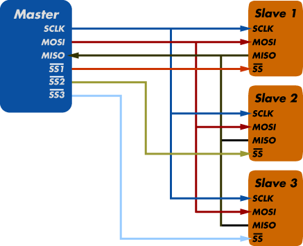
This is how SPI works:
- there is a master
- there is one or more slaves
- notice, that there are only 4 pins going into each slave
This is what the pins do:
- SCLK is the clock line. Very important. It synchronises the Master and the Slaves to exchange information at the same speed.
- MOSI - Master Out, Slave In. Data from master to slave. This goes from master mosi to slave (lcd) SCR_DIN as you figured out
- MISO - data in the opposite direction
- SS - slave select. In order to tell WHICH slave is supposed to get the next command or data, the Master pulls this pin LOW to talk to each slave. Only one slave should be active at the same time. All other SS lines should be HIGH. SS is often also called CS (cable select) or EN (enable)
Now, you notice now that there is NO DC line in this picture.
How can it be ?
The DC or D/C is a feature, that is specific to the 5110 graphics driver chip. It has nothing to do with the SPI protocol. Therefore, the DC pin can be ANY NORMAL PIN you choose from the Master side. You choose what pin it is, by specifying it in the program code.
So you see, there is no one answer to your question. You need to look at the code and/or copy paste it here to find out what pin on the Master is the DC.
Duhjoker Thu Sep 01, 2016 1:28 am
And summoner123 had this to say......
Great work guys I think I might be able to set my LCD up to the teensy 3.2 now!!!
I poured over the over all the info for days and missed that completely. Thank you for the extra eyes!!!!
Summoner123 wrote:Hi DuhJoker.
It will be more simply if we have a Library to interface your display with the Teensy. rsrs
Reading the datasheet at the "Interface Logic Pins" section I have found that:
So the Data/Comand pin is the "RS" pin....

Great work guys I think I might be able to set my LCD up to the teensy 3.2 now!!!
I poured over the over all the info for days and missed that completely. Thank you for the extra eyes!!!!
Duhjoker Thu Sep 01, 2016 1:40 am
I also found these.......
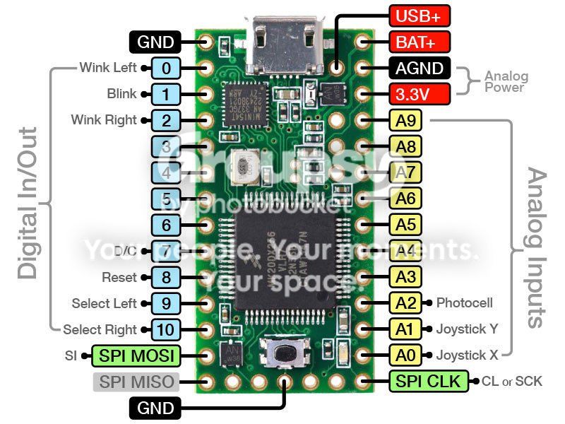
Front of teensy
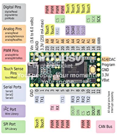
This is the back.... Look at those inputs!!!!!
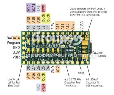
Found this too showing where miso and mosi actually are on the board the green parts are for the spi.
Front of teensy
This is the back.... Look at those inputs!!!!!
Found this too showing where miso and mosi actually are on the board the green parts are for the spi.
Duhjoker Thu Sep 01, 2016 3:42 am
Ok so I think I have the correct pin out for my wiring. It goes like this.....
RS = data command SCR_DC
RST = reset SCR_RST
MOSI = data in SCR_DIN
WR = write enable Needed by the LCD
CS = chip select SCR_CS
RD = read enable Needed by the LCD
CLK= SCR_CLK
5v in
GND
I used the info from the folks above, the GB schematic, the gb .settings file and the pin out offered by the LCD_2000_7775. I'm not seeing any thing about needing a resistor in the LCD info but I could be missing it though I think that's just needed for the Nokia 5110 LCD.
Do I need MISO, I'm not seeing it used for the GB schematic.
RS = data command SCR_DC
RST = reset SCR_RST
MOSI = data in SCR_DIN
WR = write enable Needed by the LCD
CS = chip select SCR_CS
RD = read enable Needed by the LCD
CLK= SCR_CLK
5v in
GND
I used the info from the folks above, the GB schematic, the gb .settings file and the pin out offered by the LCD_2000_7775. I'm not seeing any thing about needing a resistor in the LCD info but I could be missing it though I think that's just needed for the Nokia 5110 LCD.
Do I need MISO, I'm not seeing it used for the GB schematic.
Duhjoker Thu Sep 01, 2016 6:33 am
Ok i have a pin out i think will work with the LCD to the teensy. After looking at a ton of pin outs, i learned that the uno and the teensy share the same basic pin out with the teensy having more Digital I/O's.
Mosi to mosi pin 11
RS to A2 pin 16
Rst to A0 pin 14
CS to A1 pin 15
CLK to sck pin 13
WR to pin 10
RD to pin ?
Cant figure out if i need RD its not included in anything i can find.
Mosi to mosi pin 11
RS to A2 pin 16
Rst to A0 pin 14
CS to A1 pin 15
CLK to sck pin 13
WR to pin 10
RD to pin ?
Cant figure out if i need RD its not included in anything i can find.
Duhjoker Thu Sep 01, 2016 6:45 am
I can't figure out why the RS and CS go to different pins on the LCD code example.
Can some one fact check for me I would hate to take a chance at blowing my teensy
Can some one fact check for me I would hate to take a chance at blowing my teensy
rodot Fri Sep 02, 2016 8:15 am
Hello,
You just posted 8 times in a row... please avoid multiple posts if nobody answered, you can edit an existing post if you want to append some new infos.
RD probably doesn't appear in the library because it only supports writing to the screen, not reading from it. So you can probably add a pullup resistor so it doesn't float and leave it as is.
Good luck with your project !
You just posted 8 times in a row... please avoid multiple posts if nobody answered, you can edit an existing post if you want to append some new infos.
RD probably doesn't appear in the library because it only supports writing to the screen, not reading from it. So you can probably add a pullup resistor so it doesn't float and leave it as is.
Good luck with your project !
Duhjoker Fri Sep 02, 2016 9:08 am
Sorry about that, I'll make more edits from now on if I need to add something.
My hypothesis with the LCD is that it still needs to use the same basic pins to function and communicate with the teensy the way a Nokia 5110 connects to the uno. Since it uses spi I believe that to be true. But if not please correct me.
Ok so first I wrote down the pin out using the schematic, copying the relevant info from the inside of the uno schematic , pcint0, pc0 etc (I know those don't belong together just an example off the top of my head). After finding a couple more pinouts for the teensy I then took the info from the gb scheme and transposed them over to the teensy. And it's weird I don't feel like I have it right...........
SCR_DC = A2 from the gb code / pc2 = pin 23 A9 teensy
SCR_RST = A0 from the gb code / PC0 = pin 15 A1 teensy
SCR_DIN = 11 from GB code / PB3 = pin mosi A4 or pin 11 //// future question
SCR_CS = A1 from GB code / pc1 = pin 22 A8 teensy
SCR_CLK = 13 from gb code / SCK 13 teensy
But the schematics show two more pins being used besides the power and negative pins. I thought those would be WR and RD but I guess not. Wr actually goes back to SCR_CS which is chip selection on the schematic.
Also according the transposition the mosi goes to A4 but mosi and miso are pins 11 and 12 respectively on the pin out to the teensy. Which should I use.
I noticed a crystal added in the schematics. What is this for?
My hypothesis with the LCD is that it still needs to use the same basic pins to function and communicate with the teensy the way a Nokia 5110 connects to the uno. Since it uses spi I believe that to be true. But if not please correct me.
Ok so first I wrote down the pin out using the schematic, copying the relevant info from the inside of the uno schematic , pcint0, pc0 etc (I know those don't belong together just an example off the top of my head). After finding a couple more pinouts for the teensy I then took the info from the gb scheme and transposed them over to the teensy. And it's weird I don't feel like I have it right...........
SCR_DC = A2 from the gb code / pc2 = pin 23 A9 teensy
SCR_RST = A0 from the gb code / PC0 = pin 15 A1 teensy
SCR_DIN = 11 from GB code / PB3 = pin mosi A4 or pin 11 //// future question
SCR_CS = A1 from GB code / pc1 = pin 22 A8 teensy
SCR_CLK = 13 from gb code / SCK 13 teensy
But the schematics show two more pins being used besides the power and negative pins. I thought those would be WR and RD but I guess not. Wr actually goes back to SCR_CS which is chip selection on the schematic.
Also according the transposition the mosi goes to A4 but mosi and miso are pins 11 and 12 respectively on the pin out to the teensy. Which should I use.
I noticed a crystal added in the schematics. What is this for?
Duhjoker Sat Sep 10, 2016 9:56 pm
Can someone please clue me in about the crystal n the Gamebuino schematics?
Guess not. I just can't believe no one knows the answer?
Guess not. I just can't believe no one knows the answer?
Zvoc47 Sun Sep 11, 2016 10:03 pm
I have this display too. I'm not sure how to connect it. I tried with the schematics on eBay, but I think I've broken it with 5V. It really tricked me when it said 5V which I thought was the power for the display while in fact it was the background LED. That doesn't make sense. If an Arduino works on 3.3V to satisfy the screen's VCC, why would it have a 5V power supply? Can you please tell me how you wired this thing?
Duhjoker Sun Sep 11, 2016 10:15 pm
Still kinda working on that........but if you open the the LCD_2000_7775.h and then go to hardware and choose the adafruit_gfx.h. You should find what you need there.
That's what I have used but as I haven't fixed the color library yet I have no way to test. I don't think you blew the LCD using the 5v-in, I've supplied 5v to the 5v und and it comes on.
Edit
What MCU are you using?
I don't really understand why you can't open up cpp files using arduino since it uses cpp files as libraries but you will need visual studio. I use 2015. Make you a free Microsoft account and it will bypass the trial period blocker.
Edit 2
Here's a pic of how to hook up a similar screen made by pjrc. But it's using a teensy.
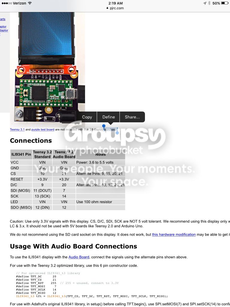
Edit 3
I don't know about connecting RST to 3.3v, I would use a SS pin
That's what I have used but as I haven't fixed the color library yet I have no way to test. I don't think you blew the LCD using the 5v-in, I've supplied 5v to the 5v und and it comes on.
Edit
What MCU are you using?
I don't really understand why you can't open up cpp files using arduino since it uses cpp files as libraries but you will need visual studio. I use 2015. Make you a free Microsoft account and it will bypass the trial period blocker.
Edit 2
Here's a pic of how to hook up a similar screen made by pjrc. But it's using a teensy.
Edit 3
I don't know about connecting RST to 3.3v, I would use a SS pin
rodot Mon Sep 12, 2016 7:52 am
The 16Mhz crystal on the Gamebuino board gives the clock to the main MCU, the ATMEGA328P, so it runs at 16 millions instructions / second.
These kind of screens usually work @3.3V... but when you buy a module on ebay, there are often level shifters to allow it to run at 5V. I've seen some that must be powered at 5V but the logic can be both 3V3 or 5V thank to the level shifters. You can say by looking at the PCB : are the screen's pin directly broken out or do they go through components ? A picture of the back of your screen could help.
On the modules I used, the backlight LEDs are powered by VCC (5V) and controlled by the BKL pin using a transistor. You can just tie it to GND if you want to keep the backlight ON or drive it using a pin. You can use a PWM pin to change the backlight intensity using AnalogWrite(). All that depends on the module you are using, so check twice :)
The .CPP (or .C or .H) files aren't opened by the Arduino IDE, but you can put some alongside your .ino file and #include them, so they will be included and compiled (it's what you do when you include a library). You will have to edit these files using an external editor, you can use your notepad, but there are better options like notepad++ or atom. Or you can use another IDE which allow to open everything (.ino, .cpp...) : there is a free Community Edition of Visual Studio and the Visual Micro plugin allows you to compile and upload your code. You can also use NetBeans with a plugin, or PlatformIO... there are plenty to choose from.
These kind of screens usually work @3.3V... but when you buy a module on ebay, there are often level shifters to allow it to run at 5V. I've seen some that must be powered at 5V but the logic can be both 3V3 or 5V thank to the level shifters. You can say by looking at the PCB : are the screen's pin directly broken out or do they go through components ? A picture of the back of your screen could help.
On the modules I used, the backlight LEDs are powered by VCC (5V) and controlled by the BKL pin using a transistor. You can just tie it to GND if you want to keep the backlight ON or drive it using a pin. You can use a PWM pin to change the backlight intensity using AnalogWrite(). All that depends on the module you are using, so check twice :)
The .CPP (or .C or .H) files aren't opened by the Arduino IDE, but you can put some alongside your .ino file and #include them, so they will be included and compiled (it's what you do when you include a library). You will have to edit these files using an external editor, you can use your notepad, but there are better options like notepad++ or atom. Or you can use another IDE which allow to open everything (.ino, .cpp...) : there is a free Community Edition of Visual Studio and the Visual Micro plugin allows you to compile and upload your code. You can also use NetBeans with a plugin, or PlatformIO... there are plenty to choose from.
Duhjoker Mon Sep 12, 2016 8:05 am
Thanks for the reply i appreciate it!! :)
Zvoc47 Tue Sep 13, 2016 2:39 pm
I'm asking about the Inhaos ST7775 display, not ST7735. I do have ST7735, though, and it works well. I've been using it with an Arduino Duemillanove derivative called Croduino.
Duhjoker Tue Sep 13, 2016 7:56 pm
Who mentiined any thing about a st7735?
Plus i could help you better if i knew the answers to the questions i asked above. Can't help unless I know what hardwares you are using.
Plus i could help you better if i knew the answers to the questions i asked above. Can't help unless I know what hardwares you are using.
Zvoc47 Wed Sep 14, 2016 2:17 pm
In the first post, I saw the ST7775 display and I said that I somehow broke it with 5V of the Arduino Duemillanove (Croduino).
Duhjoker Wed Sep 14, 2016 8:10 pm
Zvoc47 wrote:I'm asking about the Inhaos ST7775 display, not ST7735. I do have ST7735, though, and it works well. I've been using it with an Arduino Duemillanove derivative called Croduino.
No mention of an st7735 before post above on this thread.
Im trying to understand why your screen shorted. It does use both 5v and 3.3v inputs, are you sure you didn't get the two confused?
If you look at the source code for your LCD specifically the adafruit_GFX, the LCD_2000_7775.h and match them to the gamebuinos display.h and settings.h, you will find which wires need to be hooked up to work the LCD. Now since your using a different MCU than a uno R3 you will have to do some research to figure out which pins on the arduino to connect the LCD to.
It basically uses the same pin system that the regular Gamebuino UNO R3 uses with a bunch of data pins which collect and display data to the screen like in bar graphs.
You won't need those data pins since it's taking in a different type of data. Look on the first page of this thread and you will see all relevant info that has been collected including what I wrote above.
When you do get it right please share your work.If your willing, I could use a lil help with my library.
Zvoc47 Thu Sep 15, 2016 9:16 pm
Arduino Duemillanove has the ATMEGA328P microcontroller and it runs on 5V, but the eBay page of the Inhaos display ST7775 says that the I/O voltage is 3.3V or something like that. It cannot support 5V. This is why I think I broke the screen. I used the code that was in the downloadable zip file on the Inhaos website and uploaded it onto the board, but there was no picture. I tried using a lot of resistors (and failed with wrong wiring) to divide the voltage and still no success. Can you show me how you wired the Inhaos display? Can you take a picture of it?
By the way, I saw there's a shield of the display and for Arduino Uno, from Inhaos. I saw that there are lots of resistors on the I/O lines. This surely explains that resistors need to be used. I'm just going to buy a new display, a normal Arduino Uno board and the shield and see if it will work.
Are you using ATMEGA328P?
By the way, I saw there's a shield of the display and for Arduino Uno, from Inhaos. I saw that there are lots of resistors on the I/O lines. This surely explains that resistors need to be used. I'm just going to buy a new display, a normal Arduino Uno board and the shield and see if it will work.
Are you using ATMEGA328P?
Duhjoker Fri Sep 16, 2016 1:11 am
Ok I hooked up my screen directly to a 5.2v 500mah powerboost500c which is my main power. As you can see it lights up just fine. I'm still working on the rest of the wiring but I'm concentrating on the library right now.
Now I did notice a weird glitch with the grounds though. If I hook up the power to the teensy' V-in it works fine but if I attach both the Ground from the battery and the ground from the screen on the same ground pin on the teensy, it shuts both down.
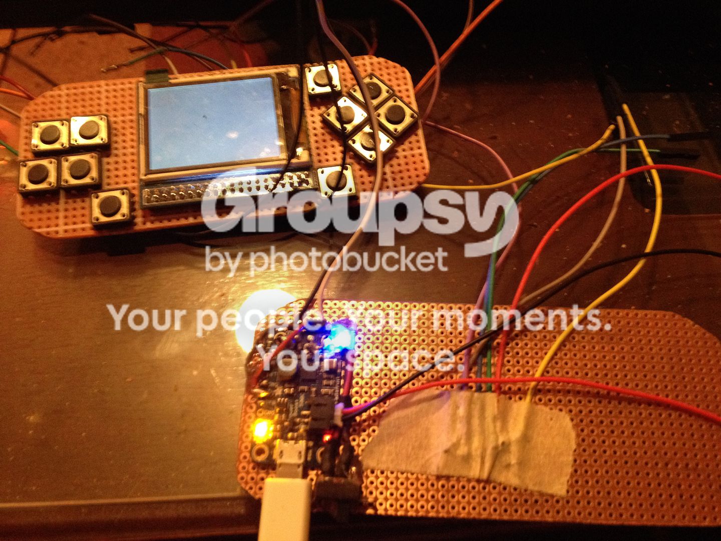
Now I did notice a weird glitch with the grounds though. If I hook up the power to the teensy' V-in it works fine but if I attach both the Ground from the battery and the ground from the screen on the same ground pin on the teensy, it shuts both down.
Zvoc47 Fri Sep 16, 2016 9:24 pm
Have you printed out any picture on the display? What is the voltage on the I/O of the display? To what voltages did you connect "3.3V" and "5V" pins of the display?
Duhjoker Sat Sep 17, 2016 12:08 am
All right man slow down just a bit, lol!
I'm having to re-invent the wheel here or at least upgrade it. This is hard for me software wise due to my in-experience and I'm looking for help every where.
But I want to try to help you since yours should be easier, Since im using a completely different MCU than you are.
1st as I have been told by various members, a regular arduino unit by itself has very lil capacity for color imaging due the memory requirements needed to render the images which will also slow your frame rate down.
This is the main reason I chose the teensy 3.2, it not only has 256k ram but a 32-bit processor. Which is plenty.
Now you have to understand that my MCU is different than a regular arduino and has the same pinouts but in different places. I can tell you my wire scheme but it won't help you since the pinout is a lil different. Since you are using a regular type arduino unit the pinout will probably be the same as the pinout as the arduino uno 3.
I will share my pinout regardless
5v in
Ground
RST = 3.3v /// aka scr_rst
CS = pin10 ///aka chip select //scr_cs
DC = pin9 ////aka RS ///scr_dc
Mosi = pin11 ///scr_din
SCK = pin13 ///aka clk
Miso = pin12
WR = A6 ////aka write enable
No I have not tried to render an image on the screen. That's what I came up with after doing the research.
All of this is already been put down in this thread but here we go.........
Open up settings.h in the Gamebuino library and look at line 70 either using notepad or a free program like visual studio express and create a free account so it bypasses the time blocker.
Write down what you see here that is the pin-out needed to hook up the nokia5110 but it also tells you what some of the needed pins you will need to wire to the arduino. These pins will also be used by the 7775 screen plus a few more.
Now open up the adafruit_gfx.cpp file and scroll down to line 55 and you will that though a couple are named different that it uses the same pinout as used by the Gamebuino settings.h file.
From thier you will have to match the pinout for the arduino uno 3 to the arduino unit you are using now, that I can't spell or pronounce.
Besides what the above tells you, RD will need to be hooked up.
My teensy like most arduino units have a 3v pin near the 5v in, so I just hook the 3v wire from the LCD to the teensy's 5v in. The 3.3v comes from the 5v in but regulated down. Applying power to this pin can give you the magic white smoke. Do Not Apply Power to 3.3v pins!!!
I'm having to re-invent the wheel here or at least upgrade it. This is hard for me software wise due to my in-experience and I'm looking for help every where.
But I want to try to help you since yours should be easier, Since im using a completely different MCU than you are.
1st as I have been told by various members, a regular arduino unit by itself has very lil capacity for color imaging due the memory requirements needed to render the images which will also slow your frame rate down.
This is the main reason I chose the teensy 3.2, it not only has 256k ram but a 32-bit processor. Which is plenty.
Now you have to understand that my MCU is different than a regular arduino and has the same pinouts but in different places. I can tell you my wire scheme but it won't help you since the pinout is a lil different. Since you are using a regular type arduino unit the pinout will probably be the same as the pinout as the arduino uno 3.
I will share my pinout regardless
5v in
Ground
RST = 3.3v /// aka scr_rst
CS = pin10 ///aka chip select //scr_cs
DC = pin9 ////aka RS ///scr_dc
Mosi = pin11 ///scr_din
SCK = pin13 ///aka clk
Miso = pin12
WR = A6 ////aka write enable
No I have not tried to render an image on the screen. That's what I came up with after doing the research.
All of this is already been put down in this thread but here we go.........
Open up settings.h in the Gamebuino library and look at line 70 either using notepad or a free program like visual studio express and create a free account so it bypasses the time blocker.
Write down what you see here that is the pin-out needed to hook up the nokia5110 but it also tells you what some of the needed pins you will need to wire to the arduino. These pins will also be used by the 7775 screen plus a few more.
Now open up the adafruit_gfx.cpp file and scroll down to line 55 and you will that though a couple are named different that it uses the same pinout as used by the Gamebuino settings.h file.
From thier you will have to match the pinout for the arduino uno 3 to the arduino unit you are using now, that I can't spell or pronounce.
Besides what the above tells you, RD will need to be hooked up.
My teensy like most arduino units have a 3v pin near the 5v in, so I just hook the 3v wire from the LCD to the teensy's 5v in. The 3.3v comes from the 5v in but regulated down. Applying power to this pin can give you the magic white smoke. Do Not Apply Power to 3.3v pins!!!
Zvoc47 Tue Sep 20, 2016 5:11 pm
I have ATXMEGA128A1U, but the development board for it has a flex cable output that leads to an adapter that I bought (I need to solder the flex cable to the adapter) and then I'm planning to wire those pins of the adapter to the Inhaos ST7775 display. However, I haven't done that and there's no ST7775 source code for XMEGA AVRs, but only for megaAVRs so this is why I tried using Arduino Duemillanove which uses the same chip as Arduino Uno (and it even runs Gamebuino stuff). I wired 5V I/O from Arduino Duemillanove and I put 5V to where it says 5V and I put 3.3V where it said 3.3V. I used the parallel interface because I like parallel interface more than serial, and parallel is fast. There was no smoke, though, but due to the 5V I/O, I think that the display is dead.
Now, I want to get some questions answered clearly. There's a 5V label and a 3.3V label on the display. If my XMEGA runs on 3.3V, which power pins of the XMEGA should I wire where? As you said that applying power to the 3.3V label will break the display, why does it even say 3.3V there then!? Should I connect XMEGA's 3.3V to the screen's 3.3V? If that's so, what should I put to the 5V label then? I don't have a 5V output on my XMEGA board.
I'm thinking about using XMEGA's External Bus Interface (which is kinda like Arduino Mega's XMEM) which is wired on the same pins where the flex cable goes so that by using the XMEGA's DMA I transfer the picture scanline by scanline. The CPU renders a scanline into a scanline buffer and the DMA transfers it while the CPU serves an interrupt or renders another scanline. I've calculated that this kind of picture updating might be fast enough for a nice gameplay. The picture will be rendered the way the old NES rendered the picture by using tile-based graphics and sprites.
I'd like to talk more about it on a separate thread.
Now, I want to get some questions answered clearly. There's a 5V label and a 3.3V label on the display. If my XMEGA runs on 3.3V, which power pins of the XMEGA should I wire where? As you said that applying power to the 3.3V label will break the display, why does it even say 3.3V there then!? Should I connect XMEGA's 3.3V to the screen's 3.3V? If that's so, what should I put to the 5V label then? I don't have a 5V output on my XMEGA board.
I'm thinking about using XMEGA's External Bus Interface (which is kinda like Arduino Mega's XMEM) which is wired on the same pins where the flex cable goes so that by using the XMEGA's DMA I transfer the picture scanline by scanline. The CPU renders a scanline into a scanline buffer and the DMA transfers it while the CPU serves an interrupt or renders another scanline. I've calculated that this kind of picture updating might be fast enough for a nice gameplay. The picture will be rendered the way the old NES rendered the picture by using tile-based graphics and sprites.
I'd like to talk more about it on a separate thread.
Duhjoker Tue Sep 20, 2016 8:01 pm
Ok there seems to have been a lil miscommunication on my part.
What I meant was do not apply power the 3.3v pin on your arduino. The 3.3v is supplied by your 5v in. Doing so will kill your arduino.
Your screen will use both the 3.3v and 5v pins.
Your arduino unit will need a 5v in, you can splice a wire from the 5v in back to the screen. It doesn't matter how it's really powered as long as you supply the right voltage.
If you arduino doesn't use 5v then you will need one that does have a 5v input
Do you have the library that summoner123 built with the tilemap routine? It's really really cheap on memory. I managed to get all the maps for Zelda together in the same sketch and it only used half the available memory. This will help
What I meant was do not apply power the 3.3v pin on your arduino. The 3.3v is supplied by your 5v in. Doing so will kill your arduino.
Your screen will use both the 3.3v and 5v pins.
Your arduino unit will need a 5v in, you can splice a wire from the 5v in back to the screen. It doesn't matter how it's really powered as long as you supply the right voltage.
If you arduino doesn't use 5v then you will need one that does have a 5v input
Do you have the library that summoner123 built with the tilemap routine? It's really really cheap on memory. I managed to get all the maps for Zelda together in the same sketch and it only used half the available memory. This will help
Zvoc47 Tue Sep 20, 2016 11:39 pm
I see. So basically, this ST7775 runs on 3.3V, but has a 5V pin because of the stupid backlight!? They could have made a 3.3V board that has a level shifter so that one could connect either 3.3V or 5V. ST7735 works on both 3.3V and 5V, I suppose. It worked on my Arduino, but not on my XMEGA when I translated the code to it.
Unfortunately, the display is no longer for sale on eBay so I have to find another one. Which one would you recommend?
Unfortunately, the display is no longer for sale on eBay so I have to find another one. Which one would you recommend?
Duhjoker Wed Sep 21, 2016 1:29 am
Actually it runs on the 5v and uses the 3.3v pin as the back light. You may not need the 3.3v back light. When I plug mine in its kinda low ligh but very visible.
Duhjoker Wed Sep 21, 2016 9:48 am
Ok ive been playing around with library. I think the first step should be getting the LCD to compile using the teensy's adafruit_GFX.h and c++ files. Which means moving a bunch of stuff from the original gfx to the teensy.
Still having problems and im starting to get frustrated so i think i might try working on the hardware tommorow using the 7775 example, doesnt matter which one.
Maybe ill feel like i accomplished something.
Im a late person so i dont start thinking properly til evening so it will prolly be around 21:00 American CST before i get back to you.
Edit: ok so I was looking at some old 8-bit game graphics when I noticed a pattern in the early games like Mario, Zelda, duck hunt and so on. It looks like they use the same colors over and over again. 16 of them to be exact.
Would it be easier, after getting the library to work, on the memory to set a 16 bit color set palette?
Still having problems and im starting to get frustrated so i think i might try working on the hardware tommorow using the 7775 example, doesnt matter which one.
Maybe ill feel like i accomplished something.
Im a late person so i dont start thinking properly til evening so it will prolly be around 21:00 American CST before i get back to you.
Edit: ok so I was looking at some old 8-bit game graphics when I noticed a pattern in the early games like Mario, Zelda, duck hunt and so on. It looks like they use the same colors over and over again. 16 of them to be exact.
Would it be easier, after getting the library to work, on the memory to set a 16 bit color set palette?
Zvoc47 Thu Sep 22, 2016 8:38 pm
I was thinking about using a pre-made 16 color pallette.
 From Pico-8.
That would simplify all rendering. Here you have all colors you'd ever want. The MS-DOS pallette sucked so bad. There was no orange. But over here, there's all colors you'd want.
You said the LCD runs on 5V, but why didn't the compiled code run on it? Is that because I used 5V on I/O? Was there a program error or something? This means that on eBay what the guy said that I/O is not on 5V is a lie, but I would like this to be confirmed. What's the correct voltage of the display's I/O?
Also, did you get any picture on the screen? You didn't answer me that question.
From Pico-8.That would simplify all rendering. Here you have all colors you'd ever want. The MS-DOS pallette sucked so bad. There was no orange. But over here, there's all colors you'd want.
You said the LCD runs on 5V, but why didn't the compiled code run on it? Is that because I used 5V on I/O? Was there a program error or something? This means that on eBay what the guy said that I/O is not on 5V is a lie, but I would like this to be confirmed. What's the correct voltage of the display's I/O?
Also, did you get any picture on the screen? You didn't answer me that question.
Duhjoker Thu Sep 22, 2016 10:13 pm
It says on the inhaos that the screens IO uses anything from 1.65v to 3.3v. Other than I honestly don't know. I planned on working on it yesterday but got busy with the library again. I don't know about supplying power to your board other than the 5v in, all the other pins that supply power are regulated down from the 5v in. Adding power to any other part or pin to the board could burn it.
Ok I looked at your board and it uses the same pinout as the Uno r3 so what I think you should do is use the pinout for 5110 to the uno. Then instead of trying to compile one of the pre are sketches, write a sketch that will simply display a bitmap image.
Ok I looked at your board and it uses the same pinout as the Uno r3 so what I think you should do is use the pinout for 5110 to the uno. Then instead of trying to compile one of the pre are sketches, write a sketch that will simply display a bitmap image.
Zvoc47 Thu Sep 22, 2016 11:13 pm
So basically, you're supplying 5V to the screen while the I/O is supplied with 3.3V? That sounds very weird. By the way, I want to use the parallel 8-bit interface, not the serial interface.
Duhjoker Thu Sep 22, 2016 11:38 pm
Nooooooo!!! I'm supplying 5v to the arduinos 5volt-in then splicing another wire into the 5v to run to the 5v on the LCD. Any thing that runs of 3v gets connected to the 3.3v pin on the arduino. There is only one voltage in the rest of the pins that need voltage get it from the Arduino supplied 5 volts in after being regulated down.
The only arduino I know of that uses two power inputs are the botboarduino by Lynxmotion which uses a 9v battery for the logic and a 6v for powering servos.
The only arduino I know of that uses two power inputs are the botboarduino by Lynxmotion which uses a 9v battery for the logic and a 6v for powering servos.
Duhjoker Thu Sep 22, 2016 11:56 pm
This is an example::: the not board listed above has two power inputs me for logic one for servos.
If I try to hook up a ps2 controller to the board I would have to supply 3.3v to the Reciever head. So in order to do this I run the wireless Reciever head to the 3.3v on the botboarduino.
You need to supply voltage to both voltage inputs on the LCD screen. The 5v in can be run straight from the battery while the 3v gets it from the 3.3v pin.
Your IO things are inputs that can be used as buttons or what ever. I think there is even a pull up resistor attached to the io pins which will drop the input low and register a button press.
If you have a multimeter you test your io for voltage to see if it's high at 3.3 or low at 1.65
First try to get it display an image using the normal way. When you can do that then we can talk about how to use the io.
If I try to hook up a ps2 controller to the board I would have to supply 3.3v to the Reciever head. So in order to do this I run the wireless Reciever head to the 3.3v on the botboarduino.
You need to supply voltage to both voltage inputs on the LCD screen. The 5v in can be run straight from the battery while the 3v gets it from the 3.3v pin.
Your IO things are inputs that can be used as buttons or what ever. I think there is even a pull up resistor attached to the io pins which will drop the input low and register a button press.
If you have a multimeter you test your io for voltage to see if it's high at 3.3 or low at 1.65
First try to get it display an image using the normal way. When you can do that then we can talk about how to use the io.
Zvoc47 Fri Sep 23, 2016 12:31 am
I just don't know why are you always talking about the stupid 5V IN. I don't use that pin. I power my Arduino via USB.
Here was my scheme when I connected the LCD
// pin definition for the Uno
#define cs 11
#define wr 10
#define rs 12
#define D0 9
#define D1 8
#define D2 7
#define D3 6
#define D4 5
#define D5 4
#define D6 3
#define D7 2
5V <> 5V
3.3V <> 3.3V
I used TFTDisplayText_UNO.ino and there was no image on the display. The Arduino's I/O pins supplied 5V, but the LCD can only take 3.3V which means that it definitely cannot be powered by 5V as you say and take 3.3V as the backlight. It doesn't make sense if there's 5V for the LCD and not 5V I/O of the LCD. I'm really confused and I feel like dropping the project of this display from the frustration. I simply cannot realize what kind of voltage I need to have there. By the way, the new LCD on eBay and its adapter which has resistors to correct the 5V I/O voltage to 3.3V are all sold out which means that I cannot buy them anymore. I don't know when they'll be back in stock, but that's the only seller who sells those displays. So sad.
Anyways, do you have any idea of some better LCD which has 4-bit color with a 16-bit color pallette with which I could achieve the pallette that I have included in my pre-previous post?
Here was my scheme when I connected the LCD
// pin definition for the Uno
#define cs 11
#define wr 10
#define rs 12
#define D0 9
#define D1 8
#define D2 7
#define D3 6
#define D4 5
#define D5 4
#define D6 3
#define D7 2
5V <> 5V
3.3V <> 3.3V
I used TFTDisplayText_UNO.ino and there was no image on the display. The Arduino's I/O pins supplied 5V, but the LCD can only take 3.3V which means that it definitely cannot be powered by 5V as you say and take 3.3V as the backlight. It doesn't make sense if there's 5V for the LCD and not 5V I/O of the LCD. I'm really confused and I feel like dropping the project of this display from the frustration. I simply cannot realize what kind of voltage I need to have there. By the way, the new LCD on eBay and its adapter which has resistors to correct the 5V I/O voltage to 3.3V are all sold out which means that I cannot buy them anymore. I don't know when they'll be back in stock, but that's the only seller who sells those displays. So sad.
Anyways, do you have any idea of some better LCD which has 4-bit color with a 16-bit color pallette with which I could achieve the pallette that I have included in my pre-previous post?
Duhjoker Fri Sep 23, 2016 12:50 am
I really dont know what to tell you. I keep saying the same thing over and over again but your second guessing me. The screen does need both the 5v and the 3.3v. ive hooked mine up supplying bith voltages.
You also dont need to use all thise data pins unless they are connected to some kind of data gatherer like an oil sending unit. But you arent building a type of guage so you will need to adapt the software to use miso and mosi and everything else gamebuino uses.
You also dont need to use all thise data pins unless they are connected to some kind of data gatherer like an oil sending unit. But you arent building a type of guage so you will need to adapt the software to use miso and mosi and everything else gamebuino uses.
Duhjoker Fri Sep 23, 2016 1:48 am
Don't give up on your project!!! There is a way to do what we want but you have to undestand that this product is brand new to the market and only like me and you and few other people are trying to fix it to work.
WE have to be the innovators. No one else is goon do this for us.
I didn't mean to sound rude or mean in the above post I'm just a lil frustrated. Not at you but the situation. It shouldn't be this hard for either one of us.
Have you tried the arduino forums. There are plenty of knowledgable folks there too that might be able to help you better than I can. I want help dearly because by helping you I help myself. But let's be honest I've been working on the library because I'm stuck at the wiring part myself.
Best thing to do when your stuck is just to put it down for a while and concentrate on something else. Your problem will still be in the back of your mind but changing your focus will allow you to see things more clearly when you go back.
WE have to be the innovators. No one else is goon do this for us.
I didn't mean to sound rude or mean in the above post I'm just a lil frustrated. Not at you but the situation. It shouldn't be this hard for either one of us.
Have you tried the arduino forums. There are plenty of knowledgable folks there too that might be able to help you better than I can. I want help dearly because by helping you I help myself. But let's be honest I've been working on the library because I'm stuck at the wiring part myself.
Best thing to do when your stuck is just to put it down for a while and concentrate on something else. Your problem will still be in the back of your mind but changing your focus will allow you to see things more clearly when you go back.
Zvoc47 Fri Sep 23, 2016 12:10 pm
Alright. The only way to get the LCD working is to get that LCD board and the adapter board. I suppose that I was supposed to buy the adapter board and not just the LCD board since connecting without the adapter causes the I/O pins to be 5V instead of 3.3V like how the adapter would lower it. Now we have to wait for the LCD to get back in stock and wait some more to get it delivered. I don't think I'll have time for this project. In a week, I'll have to go to college and I don't know how things will go.
I can tell you some other info, though. When I used ST7735 and sent bytes over a fast hardware SPI to fill the screen with an 8x8 tile, it took like 1/3 of a second to do it. But I think that using the parallel interface would speed up the process.
I know that then there wouldn't be enough pins for Gamebuino stuff, but it doesn't matter because I intended to use this display on an XMEGA. But if XMEGA has no 5V while 5V is required by the display, I think it's impossible to do this project. Also, if my XMEGA game console is going to have a 4.2V battery, that would be too low for 5V to work. I really don't know what to do. I'm thinking about getting another display type maybe.
I can tell you some other info, though. When I used ST7735 and sent bytes over a fast hardware SPI to fill the screen with an 8x8 tile, it took like 1/3 of a second to do it. But I think that using the parallel interface would speed up the process.
I know that then there wouldn't be enough pins for Gamebuino stuff, but it doesn't matter because I intended to use this display on an XMEGA. But if XMEGA has no 5V while 5V is required by the display, I think it's impossible to do this project. Also, if my XMEGA game console is going to have a 4.2V battery, that would be too low for 5V to work. I really don't know what to do. I'm thinking about getting another display type maybe.
Duhjoker Fri Sep 23, 2016 9:22 pm
Dont get discouraged. There is way to do this. Im gonna keep working on it.
Why not use a smaller board with more capability? My teensy is 5v in with a 3.3v pin and 1.65v coming out of the serials and has a pull up resistors on the IO for button play.
Any way take a break, ill keep working and stay in contact and will share my findings when i can.
Why not use a smaller board with more capability? My teensy is 5v in with a 3.3v pin and 1.65v coming out of the serials and has a pull up resistors on the IO for button play.
Any way take a break, ill keep working and stay in contact and will share my findings when i can.
Duhjoker Mon Oct 10, 2016 3:37 am
Been a while since I worked on hardware and I didn't really feel like working on code much today so started getting the rest of the wires soldered to the Teensy so I can start testing. I used the chart for the LCD on page two that has the pic of their screen. Pretty straight forward on which SPI pins to use though I used the alternates 20 & 21.
I was having trouble with being able to manipulate the MCU and its wires with out worry of them falling off so I made all the wires facing the opposite of the USB and then used a lil hot glue to bind the wires together and secure them on thier pins. It has the added option of insulating between the messy solder points.
It's a mess but fortunately I thought ahead and wrote down which wires were what before gluing them. Stupid me soldered the wires straight from the screen to the MCU with out thinking about testing. The 3.3v pin on the screen is powered by the 3.3v pin at the bottom of the unit. Which also has the ground for it. Hooked up the 5v from the 5v in and it comes on ok but not bright. That's fixed by the code though.
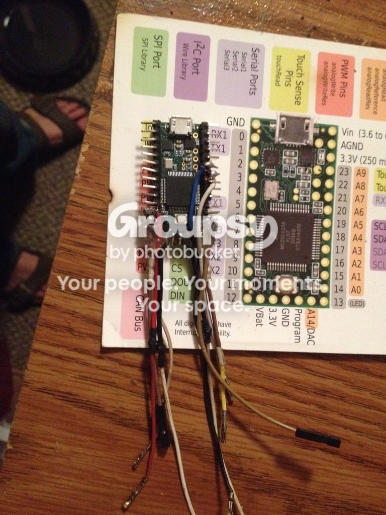
If your still out there Zvoc47 I will edit this post with in the next couple days so keep an eye on it.
I was having trouble with being able to manipulate the MCU and its wires with out worry of them falling off so I made all the wires facing the opposite of the USB and then used a lil hot glue to bind the wires together and secure them on thier pins. It has the added option of insulating between the messy solder points.
It's a mess but fortunately I thought ahead and wrote down which wires were what before gluing them. Stupid me soldered the wires straight from the screen to the MCU with out thinking about testing. The 3.3v pin on the screen is powered by the 3.3v pin at the bottom of the unit. Which also has the ground for it. Hooked up the 5v from the 5v in and it comes on ok but not bright. That's fixed by the code though.
If your still out there Zvoc47 I will edit this post with in the next couple days so keep an eye on it.
Zvoc47 Thu Oct 13, 2016 11:58 am
When you wire that, tell me. Will you be using the parallel interface or the serial interface? I wish you could use the parallel one so that I can see how you did it. By the way, why are your pins bent and why didn't you use jumpers, but instead soldered the pins? It's going to be harder to make a parallel wiring now.
Duhjoker Thu Oct 13, 2016 8:49 pm
The pins are bent that way so its as thin as possible and i can fit it inbetween two pieces of breadboard. The wires i soldered are for the spi. I know nothing about the parellel way to hook it up or how it works. I started out using jumpers but they kept falling off the pins so i went ahead and soldered the spi stuff plus the 3.3v and ground pins at the bottom for the screen.
rodot Wed Oct 19, 2016 6:52 am
You could have made a socket on a vera board using female header ? Because here if anything goes wrong you'll have to re-wire the whole thing on a new teensy :/
Duhjoker Wed Oct 19, 2016 7:16 am
Well according to my research it uses the same pinout as an uno or mini. The only pins I have wired are the SPI pins and I have a few alternates of those that I haven't wired, just in case.
How about a lil help with the Ted turnerazation of the draw bitmap and tilemap functions please!!!!
How about a lil help with the Ted turnerazation of the draw bitmap and tilemap functions please!!!!
naed Sun Nov 20, 2016 11:55 pm
Hows your hardware project coming along?
Do you have any updated pics?
Do you have any updated pics?
Duhjoker Mon Nov 21, 2016 12:29 am
Its coming.....
I have everything wired i just neen to hook it up and see if it works. Thinking about moving up to a teensy 3.6. Its a lil longer due to the sd card but it has 1mb of flash to go with the 32-bit processor and i wont have to add another piece to the hardware.
Every thing should work though.
I have everything wired i just neen to hook it up and see if it works. Thinking about moving up to a teensy 3.6. Its a lil longer due to the sd card but it has 1mb of flash to go with the 32-bit processor and i wont have to add another piece to the hardware.
Every thing should work though.
naed Mon Nov 21, 2016 8:20 am
Good good, nice to hear progress is being made on this and looking forward to seeing if you get this working with your custom library
Duhjoker Thu Nov 24, 2016 7:13 am
Ok I'm re-investigating a way to do bitmaps. I'm thinking if I can load the bitmaps (either full color or monochrome) from an SD I could I could save on Progmem which means building games that can take full advantage of the 32-bit processor.
I'm also thinking of buying an etching kit and try to prototype a board. The problem with the teensy and using it on a PCB is that I still have to be able to solder wires to the lil pads on the under side for the buttons. Plus you need the button to load the sketch.
I might be able to make some thing where I can drop Teensy in with pads on the other side where each button wire would connect to the board and to the PCB. If that makes sense to you. Then I could drill the hole that you could use to poke the button when flashing.
Any way........ I started playing with the hardware tonight and spent an hour trying to use the out to battery wires instead of the draw current wires on an adafruit power boost before I finally figured it out.
I've got the power soldered to the board. I connected the 3.3v to the same on the teensy and the 5v running to the teensy's 5v in and here's the weird thing though it's probably correct. I'm getting most definitely assured that the 3.3v is for contrast. If I connect the 3.3v to 5v it lights up nice and bright. If I connect it to 3.3v nothing happens til I add the 5v to the 5v in on the teensy. Then it comes on but not bright.
I'm also thinking of buying an etching kit and try to prototype a board. The problem with the teensy and using it on a PCB is that I still have to be able to solder wires to the lil pads on the under side for the buttons. Plus you need the button to load the sketch.
I might be able to make some thing where I can drop Teensy in with pads on the other side where each button wire would connect to the board and to the PCB. If that makes sense to you. Then I could drill the hole that you could use to poke the button when flashing.
Any way........ I started playing with the hardware tonight and spent an hour trying to use the out to battery wires instead of the draw current wires on an adafruit power boost before I finally figured it out.
I've got the power soldered to the board. I connected the 3.3v to the same on the teensy and the 5v running to the teensy's 5v in and here's the weird thing though it's probably correct. I'm getting most definitely assured that the 3.3v is for contrast. If I connect the 3.3v to 5v it lights up nice and bright. If I connect it to 3.3v nothing happens til I add the 5v to the 5v in on the teensy. Then it comes on but not bright.
Duhjoker Fri Nov 25, 2016 4:23 am
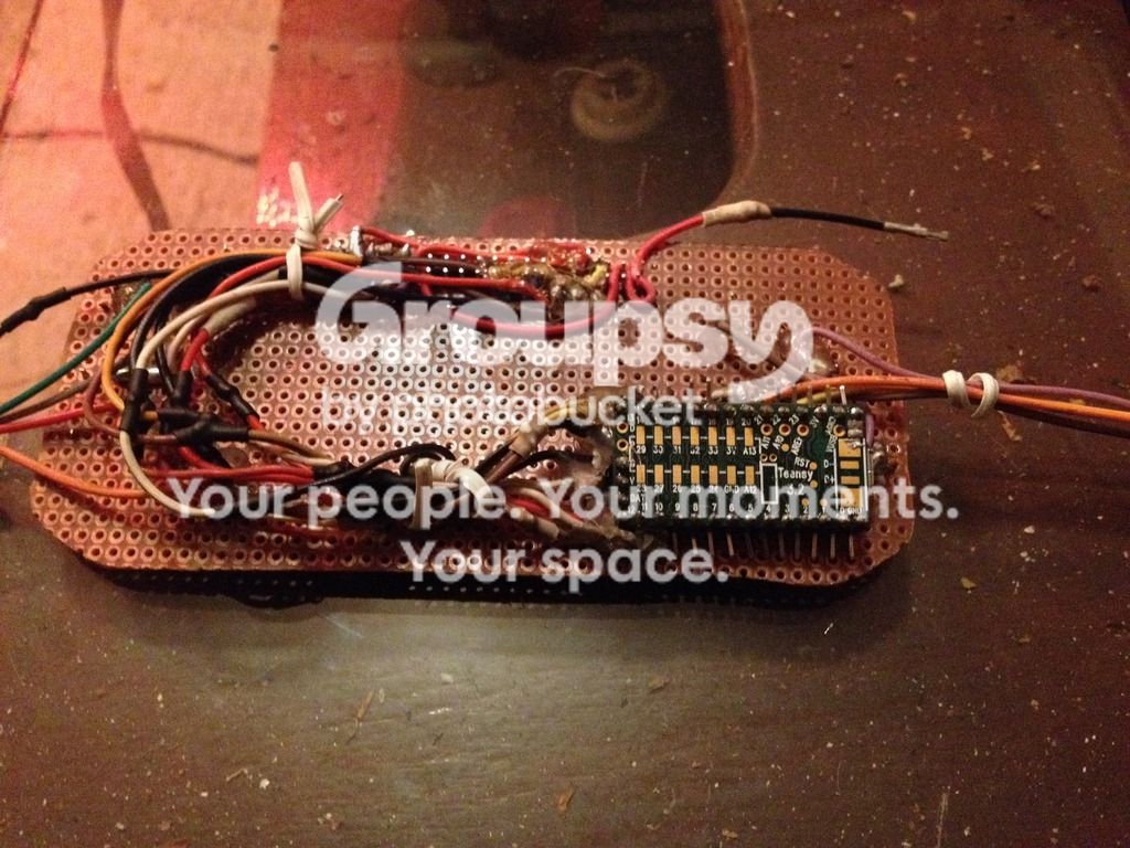
All right guys I finished hooking every thing up but have not tested set up yet. It's a mess of wiring and I have no idea if I have it hooked up right. Most of it was pretty self explanatory though. Mosi goes to mosi, miso to miso, CS to CS, clk to SCK, etc. the two wires I'm worried about are rs and wr, I have them both on a CS pin.
Duhjoker Mon Jan 02, 2017 9:02 am
Ok so i upgraded to the teensy3.6 with its 1mb of progmem and sd card slot built in and i also decided to switch screens as well. I looked online and found another cheap but widely available 2.4 inch mcufriend st7789 or ili9341. The resolution has a whopping 320 x 240 pixels. Perfect for 16 bit graphics at 20 x 15 tiles.
The library includes a function called tft.pushcolors() that goes with a bitmap function to what i assume shows full color bitmaps. But im unsure where or how to store the bitmaps for the function.
The library includes a function called tft.pushcolors() that goes with a bitmap function to what i assume shows full color bitmaps. But im unsure where or how to store the bitmaps for the function.
naed Mon Jan 02, 2017 4:04 pm
I'm excited to see a working model of this
Duhjoker Thu Jan 05, 2017 9:38 am
Me too man! Me too!!!
Ok so the main problem with testing the inhaos screen was due to poor soldering technique. I just learned a couple years ago but im still jot to good. Any way when i try to solder the pins i do ok not soldering two or more together but the distance between solder joints on the bread board are close enough that it was screwing around with it.
So i had an idea!!! I can print out something like a SNES controller and modify it to hold a 2.4 tft and buttuns and such. I figure i can cram all thats needed plus 3 500mah batteries inside. I can solder it better this way is my point though.
Plus it will have that retro look!!!!
Ok so the main problem with testing the inhaos screen was due to poor soldering technique. I just learned a couple years ago but im still jot to good. Any way when i try to solder the pins i do ok not soldering two or more together but the distance between solder joints on the bread board are close enough that it was screwing around with it.
So i had an idea!!! I can print out something like a SNES controller and modify it to hold a 2.4 tft and buttuns and such. I figure i can cram all thats needed plus 3 500mah batteries inside. I can solder it better this way is my point though.
Plus it will have that retro look!!!!
Duhjoker Fri Jan 06, 2017 5:29 am
Did some looking on thingiverse and found a case that will do for now. I didnt print it all out but if i can figure out how to edit it the thong might be perfect. And it will still be pocket sized!!!!
Edit 04:30 AM
Well i stayed up and did some tweaking. I was able to stretch the case enough so the screen fits in rather well. It will need to be deeper though. I just hate that its so long in order to fit the screen and the buttons. Oh well this will work for now. I did find an SNES controller .stl file but it will have to be severely edited to work. It will need widening, deepening and lengthening. But i think it will look bad a$$!!!
Edit:::
Managed to get it stretched right but still needs some modification. Its actually for a pi grrl zero but it suits my purpose for now. Any way the PG had turrets for the screen so i had to trim those down. I also couldnt figure out how to manipulate the opening so it needs a lil cutting so the whole screen fits top and bottom.
Left and right are perfect though. Gave it just enough room on either side to hold bread board rectangles for the buttons and d-pad. The shoulder buttons will be the easiest since the tactile switches will fit perfectly.
Included in the design is a place i can mount a Mini to 2.0 usb so i dont have to take it apart to flash new sketches. And then i can drill a hole for the teensys load button. It even has the place to mount the adafruit power boost 500 or 1000.
But this is temporary.....too plain. I want the case to resemble an snes controller.
Any way heres a pic of the screen inside
Edit ::: 1/12/17
Well I just finished the new library for use with the mcufriend LCD. It's pretty basic but I kept mouginos draw from sd commands and everything but I DID NOT add the UFTGLUE example with the pushcolors to the library as planned....yet. It's in the library but not added to a .h file. I also combined the serial and shield .h files to the Display files .h.
Still need some help to update the sound to ARM.
Edit:: 1/12/17
Just finished adding the UFTGLUE bits. So full color bitmaps can be displayed.
So now we can draw RGB monochrome bitmaps. The same for the tilemap a draw From SD function and a draw multicolored bitmap commands.
Is there any thing else I need to add?
Edit 04:30 AM
Well i stayed up and did some tweaking. I was able to stretch the case enough so the screen fits in rather well. It will need to be deeper though. I just hate that its so long in order to fit the screen and the buttons. Oh well this will work for now. I did find an SNES controller .stl file but it will have to be severely edited to work. It will need widening, deepening and lengthening. But i think it will look bad a$$!!!
Edit:::
Managed to get it stretched right but still needs some modification. Its actually for a pi grrl zero but it suits my purpose for now. Any way the PG had turrets for the screen so i had to trim those down. I also couldnt figure out how to manipulate the opening so it needs a lil cutting so the whole screen fits top and bottom.
Left and right are perfect though. Gave it just enough room on either side to hold bread board rectangles for the buttons and d-pad. The shoulder buttons will be the easiest since the tactile switches will fit perfectly.
Included in the design is a place i can mount a Mini to 2.0 usb so i dont have to take it apart to flash new sketches. And then i can drill a hole for the teensys load button. It even has the place to mount the adafruit power boost 500 or 1000.
But this is temporary.....too plain. I want the case to resemble an snes controller.
Any way heres a pic of the screen inside
Edit ::: 1/12/17
Well I just finished the new library for use with the mcufriend LCD. It's pretty basic but I kept mouginos draw from sd commands and everything but I DID NOT add the UFTGLUE example with the pushcolors to the library as planned....yet. It's in the library but not added to a .h file. I also combined the serial and shield .h files to the Display files .h.
Still need some help to update the sound to ARM.
Edit:: 1/12/17
Just finished adding the UFTGLUE bits. So full color bitmaps can be displayed.
So now we can draw RGB monochrome bitmaps. The same for the tilemap a draw From SD function and a draw multicolored bitmap commands.
Is there any thing else I need to add?
Duhjoker Mon Jan 23, 2017 12:02 am
Success with the teensy3.6 using an ili9341 2.2tft and sumotoys library!
[youtube]
https://youtu.be/EcH8seSKnZQ
[/youtube]
Ok now that i know i have the wiring right i can try to get the gamebuino ili9341 to work with it. Kind of concerned about the listed pin out that the gamebuino.h file uses. Might give me some trouble.
Sorry crappy video!!!
Edit:::: 03:17
Ok so I started a new library so I could test as I go. I added all the bitmap stuff, tilemap and collision detection. Then I included the buttons the battery and the back light and all is good. I even just displayed a bitmap on the screen instead of the demo.
[youtube]
https://youtu.be/EcH8seSKnZQ
[/youtube]
Ok now that i know i have the wiring right i can try to get the gamebuino ili9341 to work with it. Kind of concerned about the listed pin out that the gamebuino.h file uses. Might give me some trouble.
Sorry crappy video!!!
Edit:::: 03:17
Ok so I started a new library so I could test as I go. I added all the bitmap stuff, tilemap and collision detection. Then I included the buttons the battery and the back light and all is good. I even just displayed a bitmap on the screen instead of the demo.
Zvoc47 Sat Jan 28, 2017 8:29 pm
Wow! You've really been progressing. Could you try making a framebuffer in Teensy 3.6 and use DMA to render it during VBlank? I'd like to see the max framerate that one can achieve with this since I'm buying a Teensy 3.6 and would like to know if this works.
Duhjoker Sat Jan 28, 2017 8:54 pm
Sorry the only thing i understood was bfrae buffer.
But i did get the buffer going. Before adding it the screen kept doing some weird things with drawn bitmaps. Flashing, scan lines and such. But now its solid.
All i really did was just add the buffer stuff from the original gamebuino library.
Now i need the tilemap to work. Right now its only showing a single pixel from each bitmap and they are forced together to form a collumn. Weird.
The last library is too large to post so I put a copy in my Dropbox
https://www.dropbox.com/s/aa6ipnvilvnwi ... 3.zip?dl=0
But i did get the buffer going. Before adding it the screen kept doing some weird things with drawn bitmaps. Flashing, scan lines and such. But now its solid.
All i really did was just add the buffer stuff from the original gamebuino library.
Now i need the tilemap to work. Right now its only showing a single pixel from each bitmap and they are forced together to form a collumn. Weird.
The last library is too large to post so I put a copy in my Dropbox
https://www.dropbox.com/s/aa6ipnvilvnwi ... 3.zip?dl=0
Attachments: basicSetup.zip
Zvoc47 Sun Jan 29, 2017 6:31 pm
On ST7735, I know that you can set the window to max resolution and then just send the pixels. Does this work with the ILI display? I was thinking if after drawing on the frame buffer you could just set the window and then activate DMA to send pixels over SPI to the display.
Currently I don't have an ILI display, but I do have that old ST7735 one and an Arduino UNO. Also, I cannot write private messages for some reason.
Currently I don't have an ILI display, but I do have that old ST7735 one and an Arduino UNO. Also, I cannot write private messages for some reason.
Duhjoker Thu Feb 02, 2017 5:45 am
Ok I looked up DMA and I kinda know what it is but don't know enough to answer your question.
I mean I guess it's how hard you want to push the board. Try it out first though. Run the library and have it do a few tasks like button presses Or run the graphics test.
Speaking of buttons I think I might redo the buttons with the bounce library for faster more accurate button presses.
Ok so I spent the last couple days playing with merging the Gamebuino.h and .cpp into the display file and running it that way. I'm missing the Display battery and draw character functions. They need each other to work and I don't know how to rewrite it just yet to get them both to work. I even got the set up compiled with the gb.begin but the TFT will have to be begun after calling the gb begin. If I could figure out how to change the parameters of the display begin I could fix that but I bet if I asked I would get more of what's been going on lately which isn't much.
Edit:: fixed include for the screen in the gamebuino begin.
Edit:: had to change the Gamebuino begin() to startup() because it kept giving me over loads the other way. It seems to work but the title screen doesn't come on before it shows my bitmap. I'm Sure I need to look at that again i must missing something on that one.
So now I have the every thing included in the display library but keyboard() and displaybattery due to the funky way the draw character is included in the keyboard function. I've tried updating it but it's got me stalling.
Edit:: now have the keyboard working and the display battery working. Plus the sleep works. I had to go into teensy/AVR/cores to make a simple change to the sleep file. I mention this at the top of the display file so it's very visible.
Edit:::
Ok so now that i have every thing compiling together i decided to do some tests and found some bugs. First i changed gb.begin to gb.startup since it was conflicting with my displays begin. But when i try to use the gb.startup command in my sketch, it compiles and the screen just goes bkack with no bitmaps being displayed. Titlescreen wont print test at start up.
Also the display batteryfunction in the update function also makes no display of bitmaps.
Edit:::::2/3/17
Super huge thanks to Paul stroffegen over at teensy who gave us a fix for the sound which will be mentioned in the display.h file or a read me.
I mean I guess it's how hard you want to push the board. Try it out first though. Run the library and have it do a few tasks like button presses Or run the graphics test.
Speaking of buttons I think I might redo the buttons with the bounce library for faster more accurate button presses.
Ok so I spent the last couple days playing with merging the Gamebuino.h and .cpp into the display file and running it that way. I'm missing the Display battery and draw character functions. They need each other to work and I don't know how to rewrite it just yet to get them both to work. I even got the set up compiled with the gb.begin but the TFT will have to be begun after calling the gb begin. If I could figure out how to change the parameters of the display begin I could fix that but I bet if I asked I would get more of what's been going on lately which isn't much.
Edit:: fixed include for the screen in the gamebuino begin.
Edit:: had to change the Gamebuino begin() to startup() because it kept giving me over loads the other way. It seems to work but the title screen doesn't come on before it shows my bitmap. I'm Sure I need to look at that again i must missing something on that one.
So now I have the every thing included in the display library but keyboard() and displaybattery due to the funky way the draw character is included in the keyboard function. I've tried updating it but it's got me stalling.
Edit:: now have the keyboard working and the display battery working. Plus the sleep works. I had to go into teensy/AVR/cores to make a simple change to the sleep file. I mention this at the top of the display file so it's very visible.
Edit:::
Ok so now that i have every thing compiling together i decided to do some tests and found some bugs. First i changed gb.begin to gb.startup since it was conflicting with my displays begin. But when i try to use the gb.startup command in my sketch, it compiles and the screen just goes bkack with no bitmaps being displayed. Titlescreen wont print test at start up.
Also the display batteryfunction in the update function also makes no display of bitmaps.
Edit:::::2/3/17
Super huge thanks to Paul stroffegen over at teensy who gave us a fix for the sound which will be mentioned in the display.h file or a read me.
Duhjoker Thu Feb 23, 2017 6:13 am
Ok how does the Gamebuino physically read the battery settings? Is there something special I need to do?
Duhjoker Sun Jul 16, 2017 5:09 am
Back with another update. Thanks to the great and helpful people at the PJRC I was able to fix the frame buffer to display solid images with out flashing and smooth rendering of the tilemap. All of the new functions use the writeRectNpp command that will allow up to 8 bits per pixel. That's a lot of color!!!! All functions have the frameBuffer built into the, so it's snap to turn on the frameBuffer.
I haven't updated the ESP library yet but I will soon. The only things we need now are the title screen to work and the pop up. The ESP has a type of boot loader using the Iotuz library but we still need something for the teensy.
https://youtu.be/RkjMWnHrJNM
All working libraries are listed on github just look me up. I removed the all in one due to clustefudge and inconsistencies. The ESp32 and teensy libraries are up to date. If you need an arduino board library just drop me a line.
I haven't updated the ESP library yet but I will soon. The only things we need now are the title screen to work and the pop up. The ESP has a type of boot loader using the Iotuz library but we still need something for the teensy.
https://youtu.be/RkjMWnHrJNM
All working libraries are listed on github just look me up. I removed the all in one due to clustefudge and inconsistencies. The ESp32 and teensy libraries are up to date. If you need an arduino board library just drop me a line.